![]() The goal was to minimize transmitted radio frequency distortions, under tight real-time deadlines. Using Tracealyzer, RFI Technology Solutions could evaluate various solutions to find out which ones met the requirements, writes software engineer Samuel Jaeschke.
The goal was to minimize transmitted radio frequency distortions, under tight real-time deadlines. Using Tracealyzer, RFI Technology Solutions could evaluate various solutions to find out which ones met the requirements, writes software engineer Samuel Jaeschke.
Many projects using Real Time Operating Systems (RTOSes) are highly timing critical. One missed deadline can cause system disruption or data output to be no longer relevant.
Our application is to minimize transmitted Radio Frequency (RF) distortion products for one of our products.
Our Digital Signal Processor (DSP) is controlled using a dual core processor running a separate RTOS system on each core, communicating with each other and external peripherals. The RTOS was originally chosen for the convenience of the task operations and primitives, not so much to meet hard real-time deadlines.
In a radio network, RF input signals can have multiple RF carriers and one challenge of this is the resulting inter-modulation distortion (IMD) products generated during the RF amplification process. These IMD products can impact other users on adjacent frequencies outside our allocated bandwidth and therefore we need to keep distortion below specified levels as required by radio regulation standards.
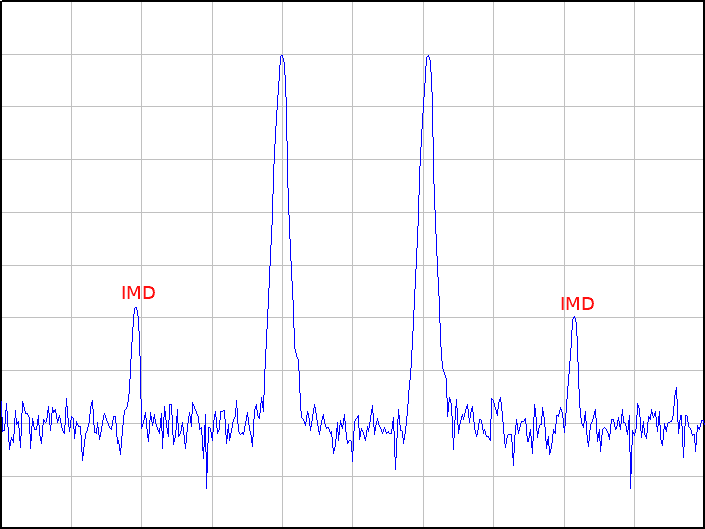
Figure 1 – Unwanted upper and lower inter-modulation distortion products shown on either side of the two wanted carriers.
One of the primary functions of the DSP controller is to capture a sample of the output signal at specific time intervals, and then perform distortion correction calculations using this sampled signal to cancel out the distortion products; the corrections are then digitally applied to the input waveform. This results in a significant minimisation of output IMD products. This process completes after a short interval, though it should happen as quickly as possible.
Reducing radio distortions
In a dynamic radio network, input signals can change their combination of carriers within an instant, causing the resulting IMD products to also change. Thus, it is important that the applied distortion correction is updated for the combination of carriers at each instant. If the necessary correction has already been calculated for this combination of carriers, then we can retrieve the correction immediately instead of recalculating. So far this occurs with a minimal but acceptable delay.
Hence there are two operations we are concerned with in the case of having a particular distortion correction already saved: 1) measuring a change in the signal carrier combination, and 2) applying the corresponding distortion correction. This will determine the latency of handling carrier changes.
There are also four operations for when we do not already have an appropriate distortion correction: 1) measuring a change in the signal carrier combination, 2) capturing the new signal, 3) processing the distortion correction (which will take some time and happens in the background), and 4) applying the distortion correction. It is acceptable that it takes some time for this to occur; however, it should not disturb the latency of the carrier changing handling described earlier.
One processor core is responsible for capturing the signal, processing the distortion correction, and applying the corrections, while the other core is responsible for measuring the signal, accepting user input, and interfacing to other devices.
Minimizing latency
Prior to using Tracealyzer we attempted to improve latency by: 1) minimizing the time mutexes are held during calculations or other lengthy activities by copying data before and copying back after, 2) changing some instances from suspending all tasks to using a more gentle mutex in protecting a shared resource, 3) adding a command buffer queue instead of waiting for a processing task to finish to submit a command, and 4) separating the command handling task from the processing task.
However, upon visualising a snapshot trace with Tracealyzer, several issues were immediately obvious. Firstly, we had to set task priority to at least 1 in our RTOS, because priority 0 tasks share the processor with the idle task! We were capping our processing task speed at 66%, as a third of the available time was spent in the idle task.
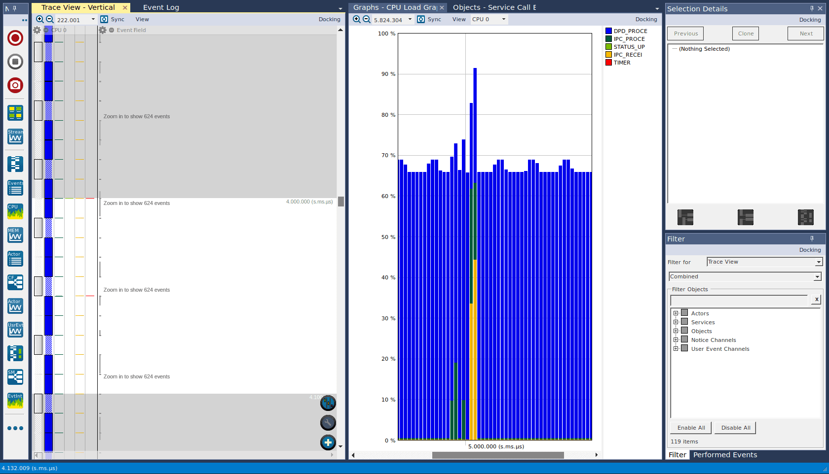
Figure 2 – The white idle task (priority 0) was stealing time away from the blue processing task (priority 0).
We had an Inter-Processor Communication (IPC) task between the two cores, which had been polling in a busy wait loop, which was intended to reduce latency – however, because it ran with high priority, in practice it would dominate the core for 9 out of 10 ms in the worst case. It achieved a 1 ms reduction in latency, but it was dominating the core and doing nothing useful for 9 ms, so it was obvious that this was not worthwhile. The delay was changed to the minimum RTOS task delay of 10 ms.
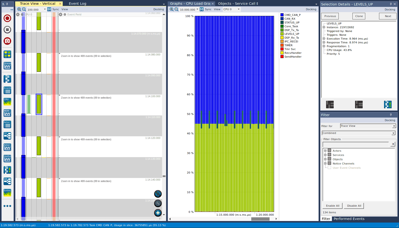
Figure 3 – A busy wait loop (light green) consumed 9 ms, halving useful processor time.
The Tracealyzer trace also exposed the chain of interactions between different tasks and cores which would determine the maximum latency in handling the carrier changes, as well as exposing several situations where high priority tasks would monopolise the processor core for 300 ms or so. It is rarely obvious by reading the code which function three levels deep might be responsible for the longest latency in a task.
A deadline every 28 ms
Another requirement, however, is that the system needs to handle Time Division Multiple Access (TDMA) signals. TDMA transmits on the same frequency:
- 28 ms of channel 1
- 2 ms pause
- 28 ms of channel 2
- 2 ms pause, etc.
Now this gives us a hard real-time requirement of 28 ms. What is the maximum latency of measuring the signal carrier combination change and applying the corresponding distortion correction? Waiting for the measuring task to become active could be up to 10 ms, then sending a message to the other core is another 10 ms, then receiving on the other core and passing to the handling task is another 10 ms, and we haven’t even applied the correction yet – this is clearly not going to work. The worst part is, applying the correction does in fact calculate values to populate a lookup table, which takes another 2.3 seconds in a debug build.
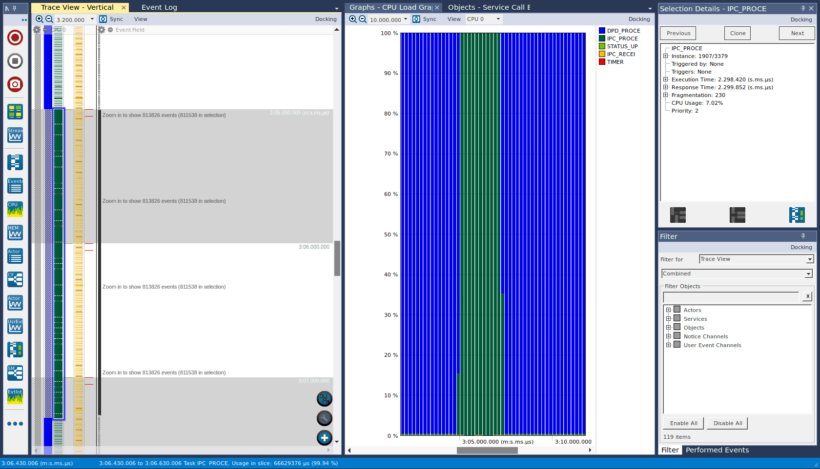
Figure 4 – For a debug build, calculating the lookup table when switching distortion corrections (green) took 2.3 s.
It is not feasible to handle carrier switches within 28 ms with so many message passing steps between tasks. So the measuring of the signal was moved to the same core as the signal capture and processing, so that the signal measuring and applying of the correction can happen within the same task. In fact, the signal capture was combined into the same step, so it captures continuously, so that on each cycle it already has the capture available if it needs to be processed (whereas capturing previously took a separate 170 ms).
Large cache saves seconds
It turns out a lot of effort is wasted when the same lookup table is calculated each time it encounters the same carrier combination – which is every 60 ms in the case of TDMA. Instead of saving the 608 KB of distortion corrections, we preserve the 72 MB set of lookup tables, so we don’t have to recalculate them. We have enough available memory, so this is acceptable. This saves us 2.3 seconds.
A further simple optimization can occur in the fortunate case where a TDMA signal is constantly switching between channel 1 and channel 2, and one carrier combination is a superset of the other. In this case, the superset combination persists as the applied correction, so there is no continuous switching back and forth between alternate corrections, and this effectively extends the period to 60 ms.
With these changes and rearrangement of the code, we were able to get a latency time of 7 ms for the common case of handling carrier combination changes, well within the required 28 ms limit.
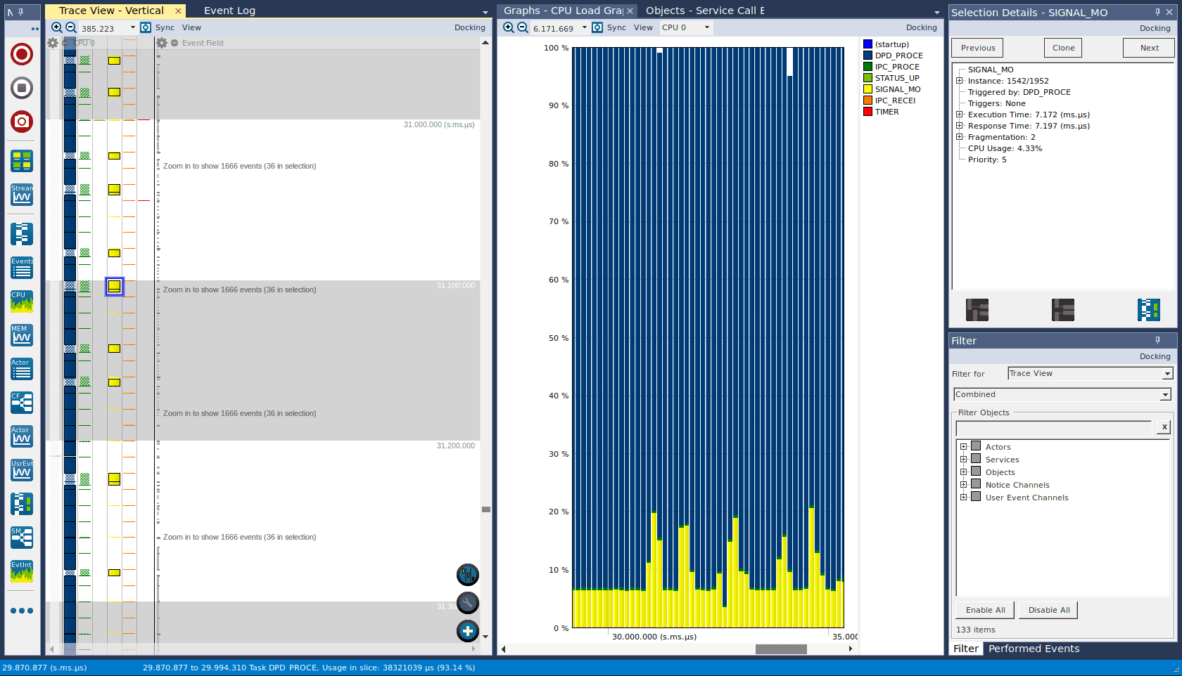
Figure 5 – Handling rapidly switching carriers (yellow) takes 7 ms.
Temporal correctness is a difficult problem, and Tracealyzer is a very helpful tool in achieving it. Without it, it’s difficult to see if you have reached your target, or even how far you are from your target. You can hope you’ve implemented it correctly – but how can you be sure?
Getting to the right design faster
In summary, Tracealyzer has helped to:
- Regain processing task CPU usage from 66% to 99%.
- Identify 50% of CPU time being unnecessarily wasted in a busy waiting loop.
- Reduce carrier switching handling time from 2.3 seconds to 7 milliseconds.
- Save us from weeks of development time and testing with tedious trace prints, which would have pushed back the product release date by the corresponding amount.
On an additional note, we have found the Percepio product developers to be very responsive. We initially had troubles building the trace instrumentation into our application, and after finding the solution, we emailed the support team one minor fix to the code and one clarification to the installation instructions. Pleasingly, both changes were made to the next product release.
This user story was submitted as a response to our Everybody Has A Story challenge in December. Every published story is awarded with a free 1-year license for Tracealyzer.