This is a part of Tracealyzer Hands On, a series of blog posts with use-case examples for Percepio Tracealyzer®.
In the last several posts, we have been examining how we can use a user event channel to trace state machine behavior. We saw that we can create custom intervals and state machines that are then plotted on our timeline. In this post, we are going to dig deeper and explore the information available in our visualization and how we can use it to better understand our application and find any defects that may exist.
Many embedded applications that involve motors make use of two different state machines; the motor state and a brake state. A motor may be in a state such as locked, stopped, low speed, medium speed and high speed. A brake state might be enabled and disabled. Obviously, if the motor is running, the brake should be disabled, otherwise we would undoubtedly start to see some smoke or at a minimum a feel a bad smell from the brake pads rubbing on the motor. Running the motor with the brakes engaged will force the motor to work harder, potentially resulting in a failure or damage to the motor. Let’s examine a trace where a motor state machine ramps up then down and verify that the brake behaves the way it is supposed to.
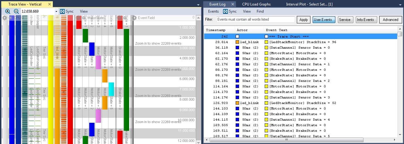
First we add user event logging for the state changes, as described in Tracealyzer Hands On #5 – Understanding your Application with User Events.
This results in two user event channels, named MotorState and BrakeState.
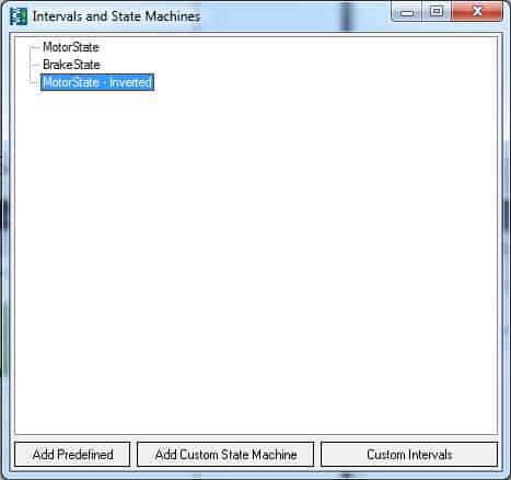
After acquiring the trace, we need to make Tracealyzer aware of this state information by defining state machines for these user event channels. As we discussed in the previous blogs, we can do this using the “Intervals and State Machines” menu option under Views. This view provides a list of all defined state machines and interval sets, initially empty, and provides three options for adding new data sets. These options include:
Add Predefined – This enables predefined intervals and state machines that Tracealyzer is aware of. For example, Tracealyzer automatically generates two interval sets for each message queue in your trace, “Message Processing” and “Queue Messages”, and if using Keil RTX5, the states of TCP sockets can be included this way.

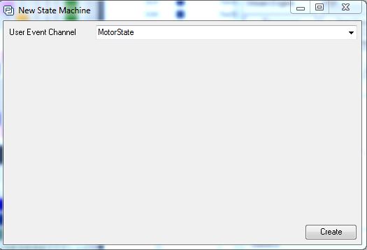
Add Custom State Machine – Here you can define a state machine using either the simple or the advanced method. The simple method assumes that there is a dedicated user event channel where only state names for the specific state machine is logged, while the advanced option makes use of regular expressions which allows you to extract state information from any event in the trace.
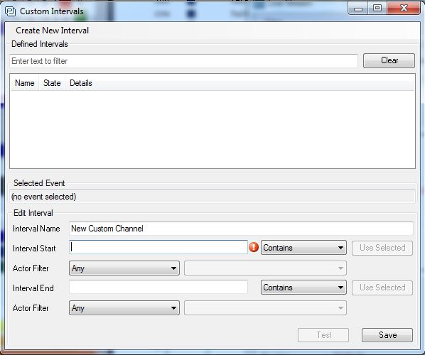
Custom Intervals – This option allows a developer to specify how to match events to produce a custom interval set. You specify strings to match for the Start and End events of the interval, “Interval Start” and “Interval End”, and intervals are then created for all matching event pairs.
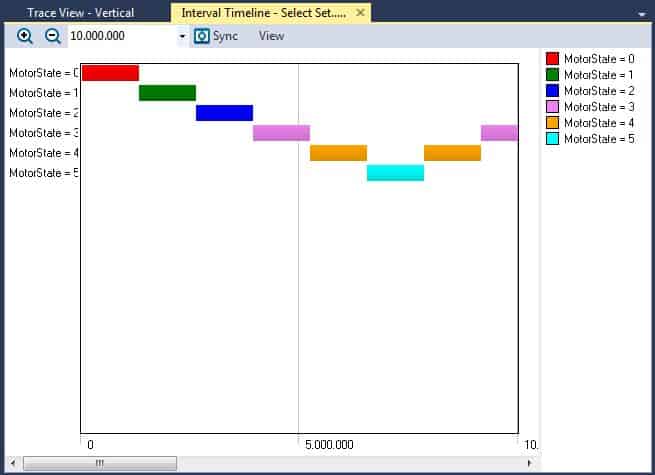
For this blog, we are just going to use Custom State Machine (the simple option) to define state machines for the BrakeState and MotorState user event channels. The result can be seen below.
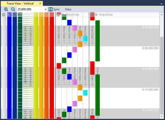
Notice on the right-hand side that you can see the MotorState and BrakeState state machines. From a visual inspection, we can see that the brake is on at the start, is released when the motor is unlocked and then engages again when the motor has stopped.
NOTE
The brake state machine has two states, 0 = ENGAGED and 1 = RELEASED.
The motor states are in increasing order 0 = LOCKED; 1 = STOPPED; 2 = LOW SPEED; 3 = MEDIUM SPEED; 4 = HIGH SPEED.
Visual inspections are great but having a more in-depth reporting system that can automatically analyze the trace is preferred. From the “Intervals and States Machines” window, a developer can right click on their custom data set and then generate a plethora of useful views and reports to help them understand their application. These include:
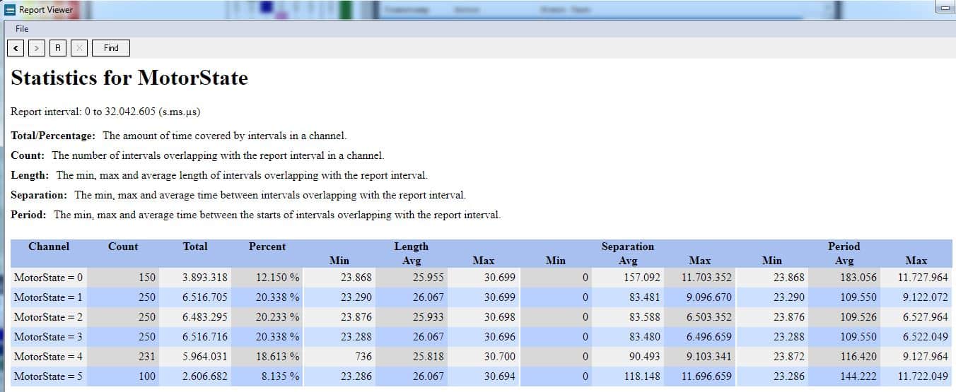
- Statistics – Generates a report for the data set, showing min, max, average lengths etc. This is useful for finding extreme cases, like the longest time between two events, and for making a more systematic analysis of the application by tracking important metrics that may change as the system evolves.
- Show Timeline – Opens a separate horizontal trace interval, for easy correlation with other horizontal views.
- Show Plot – Gives a scatter plot showing the durations of the intervals over time (much like the Actor Instance graphs for task execution times).

- Compute Overlap – Creates a report on the intersection of two data sets (i.e. is there any time when motor and brakes are on at the same time).

- Create Inverted – Generates a new “negated” data set, where you have intervals corresponding to the gaps in the original data set. This can be really useful when combined with “Compute Overlap”.
If you examine the Compute Overlap report above, you’ll notice that MotorState = 1 has overlaps with both BrakeState 0 (brake released) and 1 (brake applied). This is okay because the motor is stopped in this state. You’ll also notice that MotorState = 2 also has overlaps with both BrakeState 0 and 1, and this is not okay! MotorState = 2 is low speed motor operation, so the brake should not be applied. The “max” column reveals that this overlap is over 30 ms in the most extreme case, and you can see from the Percentage Avg column that there is a 15.2 percent overlap on average. Not much but enough to put extra stress on the system. This is obviously a bug that needs further investigation.
As we have seen in this post, state machine reporting can provide us with a wealth of information about how a state machine is behaving but also how it acts compared to other state machines. This is information that would be difficult to acquire and analyze if a developer was not using Tracealyzer. Of course, you could hook up a logic analyzer instead, but then you would need one output pin for each state, and you need to analyze the results manually. Tracealyzer makes this a lot easier.
An Expert Tracealyzer Tip
If your trace view gets too wide for your screen when adding custom state machines and intervals, you can collapse fields into a single column to make room. Just click the small green “minus” button in the header. You can also hide fields entirely by selecting the “gear” icon. You can e.g, close the “Events Field”, if it is not relevant at the moment. Restore it using “View” -> “Setup Field”, or “View” -> “View Presets”.